How To Install, Use and Maintain Portable Plasma cutting machine?
Before place order ,there are some clients who never had experienced in CNC plasma cutting machine.
Following question they are concern:
they always asked does the plasma cutter works perfectly?
How to install Portable Plasma cutting? How to Maintain Portable Plasma cutter?
Is it easy to learn?Does your machine support other langauge but English?
Yes our plamsma cutter support English,French,Spanish,Russia.
Let us take portable plasma cutter as an example:
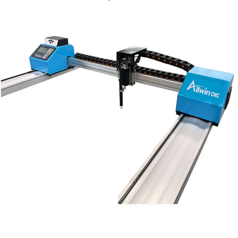
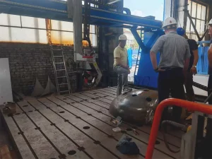
How To Install Portable Plasma cutting machine?
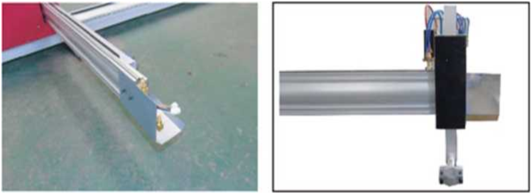
Description for Portable Plasma Machine
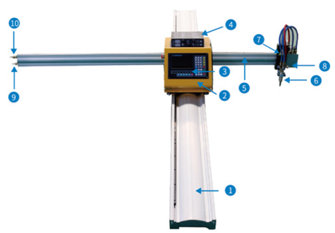
① Y rails ②Host computer
③contoller system ④height controller(THC)
⑤x rails ⑥flame torch
⑦lift body ⑧fireproof board
⑨oxygen ⑩fuels gas
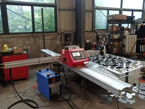
Installation step for Portable plasma cutter
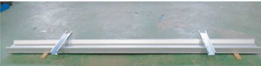
①Reverse the rails and fix the pillow to the rails. If there is a material table, the pillow is not needed
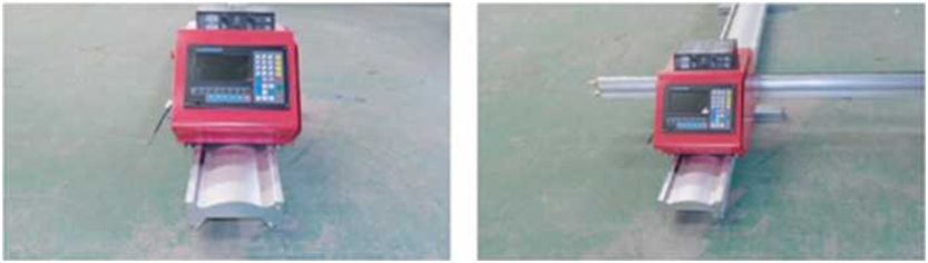
②Install the host on the rails, the guide wheels on ③Slowly insert the x rails rack face up into the host
insert the x rails rack face up into the host
both sides of the host should clamp the optical axis
on the rail, and slowly push the host. Note: The rack
on the rails is on the same side as the host switch
④Install the fireproof board and the lifting body at the
end of the x rails, and install the fireproof board between the lifting body
and the beam
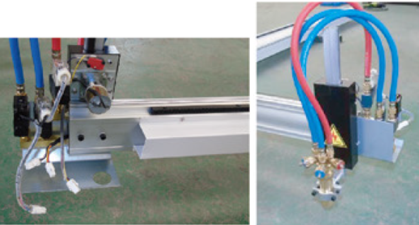
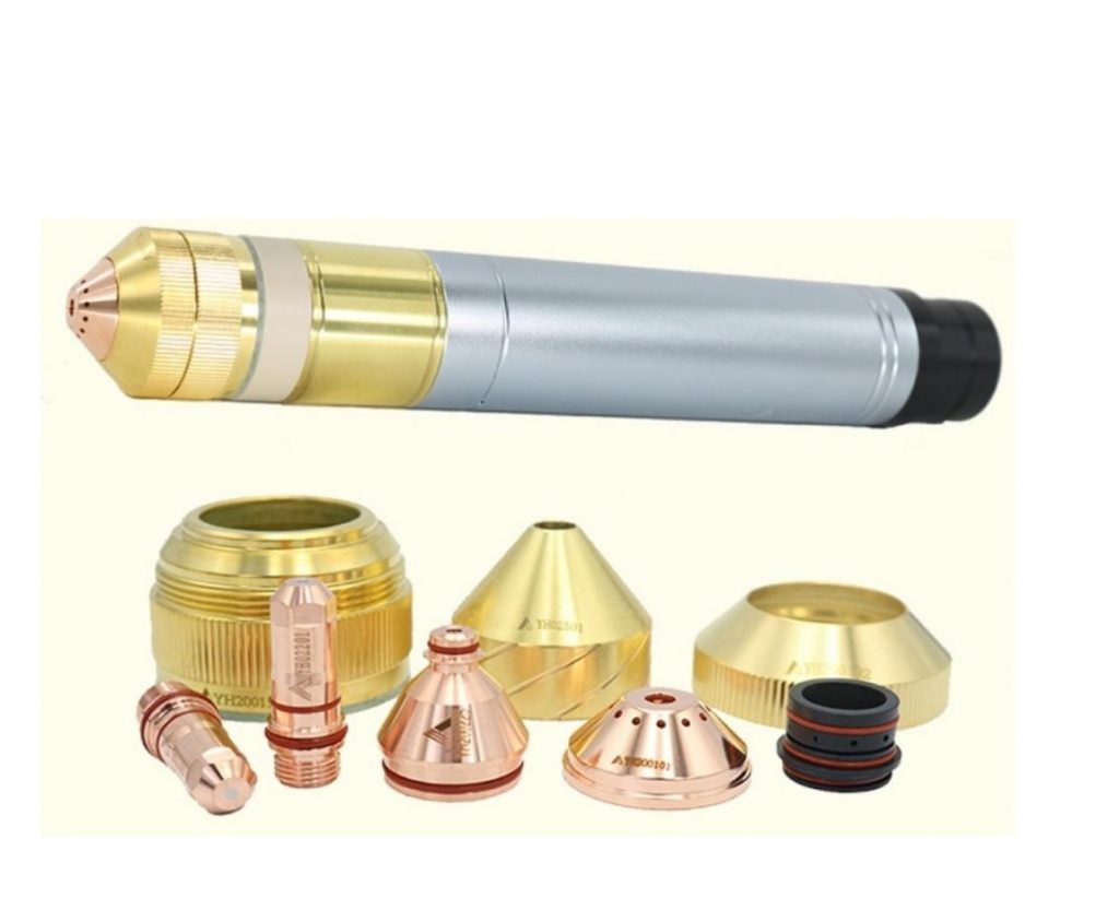
⑤Install flame cutting torch ⑥Fixed flame cutting torch
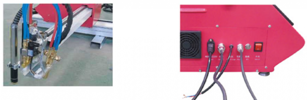
⑦plasma torch and cable ⑧Plug into socket
⑨Arc cable(Red color is +,blue color is-)
How To Use Portable Plasma cutting machine?
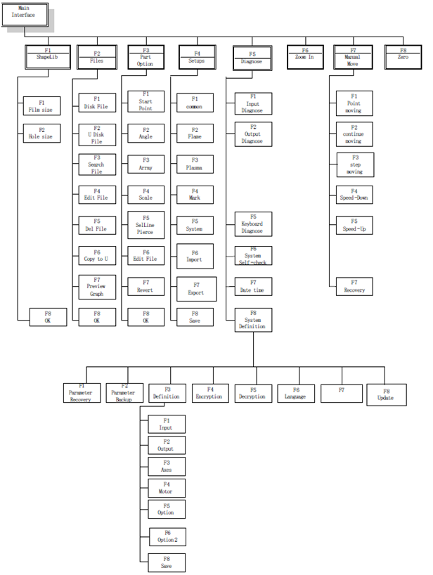
Guild Control system for Portable Cnc Plasma Cutter
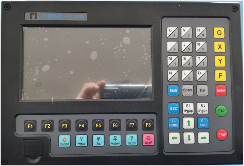
press key to enter the cutting interface, shown as follows:
【F1】:ShapeLib: Pressing F1 to enter the Shape Library including 48 common shape, and Chapter 2 Starting up 10 most of them have plate size and hole size
【F2】:Files: You can load local files, U disk files or edit, import, export and delete codes。
【F3】:PartOption: Make actions of mirroring, rotation, plate adjusting, plate arraying, selecting row and hole or code edition etc.
【F4】:Setups: Setting all parameters.
【F5】:Diagnose: Including input ports diagnosis, output ports diagnosis, keyboard diagnosis, controller self check, date setting and ports definition.
【F6】:ZoomIn: Zoom in the shape in full screen.
【F7】:Manual Move: Manually move the machine.
【F8】:Zero: Clear the coordinate of X and Y before starting cut or after cutting over.
【X】:CutSpeed: Setting the cutting speed.
【Y】:ManualSpeed: Setting the manual moving speed.
【F】:Manual: Setting the mode of manual movement including keepMov(keep movement), StepMov(step movement), ContiMov(continue movement).
【G】:StepDis: Setting the distance of the StepMov .
【Shift+N】:Before the cut running starts, set kerf compensation value.。
【shif+M】:Selecting the cutting mode including Flame Cut(flame cutting), Plasma Cu(plasma cutting), Demo run.
【START】: Begin to cut.
【Enter】: confirm
【Space: Enter cutting interface.
【STOP】:Pause, the controller can suspend all ongoing actions.。
【Esc】:Cancel the current operation。
【S↑/PgUp】: page-up key of edit interface or Torch up in other interface 【S↓/PgDn】 :page-down key of edit interface or Torch down in other inter face
【F+】:Increase the cutting speed, the speed increases by 3% every time you click
【F-】:Reduce the cutting speed, the speed decreases by 3% every time you press it
【Preheat】:flame cutting preheat,click it and turn on both propane and low pressure oxygen
【Cut Oxy】:High pressure oxygen。
【Close】:Close all solenoid valves。
Plasma Control System Key Instruction
Cutting Function For FL2100 Of Plasma Cutting Machine
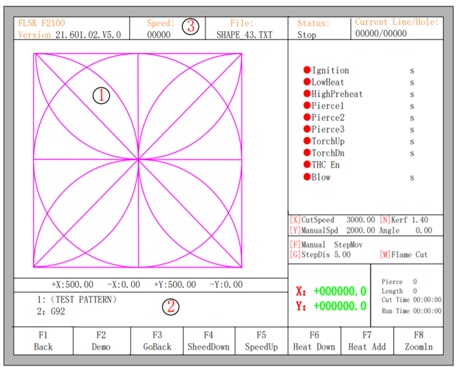
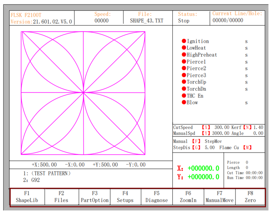
In the main interface, press the 【SPACE】to enter the cutting interface, shown as follows:
①Shows the current workpiece’s cutting path. ②Shows the G-file being processed, shows the current and next line. ③Shows the current cutting speed. during cutting or paused, you can press the keyboard’s number keys 【1】 – 【9】 to achieve quick speed regulation. For example, press the number【3】, the speed is automatically adjusted to 30%; press the number 【8】 the speed is automatically adjusted to 80%.
X shows the absolute coordinate of the torch in X direction.
Y shows the absolute coordinate of the torch in Y direction. In the cutting interface:
【X】: Modify the cutting speed.
【Y】: Modify the manual move speed.
【F】: Change the current manual move mode.
【G】: Modify the distance of step move in manual move
【START】(or【F9】): Start cutting.
【STOP】(or 【F10】): Pause, the controller can suspend all ongoing actions.
【F1】:Move back along the cutting path(I / O closed)
【F2】: Move forward along the path (I / O closed).
【F3】: Return to the starting point, i.e. the starting point of the current work piece.
【F4】: It is same to key End. Decrease the cutting speed, each decrease of 3% click rate. Decrease the rate of manual moving machine in manual mode.
【F5】: It is same to key Home. Increase the cutting speed, each 3% increase in click rate. Increase the rate of manual moving machine in manual mode. Chapter 3 Cutting Function 13
【F6】: Reduce the preheat time, skip the remaining preheat time, and the controller automatically records preheat time and the time is used until the workpiece is over.
【F7】: Increase the preheat time once 15 seconds.
【F8】: When the controller move is suspended, for selecting piercing point; when in moving, the trace display is zoom in over the full screen. Four direction keys (Up, down, left and right): manually move.
Edge Cutting / Offset Cutting / Return When the torch is not on the trace of the current work piece, it will prompt as follows
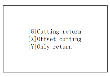
There are two reasons led to this situation:
- When the common parameter “Edge Cutting Enable” is checked and if G-file of the next processing line is M07, the system will be automatically suspended. At this time, the torch can be manually moved to any edge of the plate, press the “start” button, the system will prompt as above
- When the processing is paused, due to some reasons, it needs to move the torch out of the actual path of the work piece, the above prompt will appear.
If press【G】, the system cutting returns back to the paused point, continue to cut. This feature is particularly useful for thick steel plate, it can reduce the preheat time and increase cutting efficiency.
If press 【X】, the controller offset current point to paused point, it will continue cutting. That is, the controller offsets the cutting point. When the cutting machine paused or a power outage or any other reason, if the torch is not on the right trace of shape, the function can be used to offset the torch to the shape trace.
If press【Y】, The controller moves to the paused point quickly, and then pause. During the cutting process,
if discovering cutting torch malfunction or other issues, system needs to move the cutting tip out of cutting region to overhaul. When return to breakpoint after the maintenance, this key can be pressed. Then return to the paused point, press the【start】 button, the system automatically continues to cutting.
Instruction for Height controller(guild for new user)
Height controller for plasma cutter(THC)is very important parts.All parameter has been setted up before shippment
Figure 2. 3 F1621
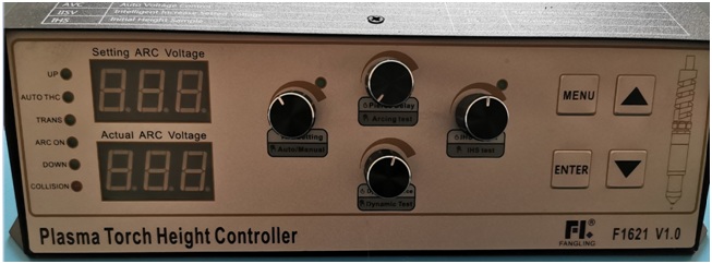
Figure 2. 3 F1621 Panel and Key Description Key Function Rotation Func- Other Rotation Function
【Arc Voltage setting】:it control the arc voltage Normally
speaking,we set 125What is Arc voltage?it means distance from the nozzles and
metal plate during cutting.
【piercing delay】it is decided by thickness of
metal plate
【Arcing Test】:In case of non-cutting and non-menu operation,
press and hold this key, plasma will start arc (arcing relay is closed), and
release this key to stop Arcing (arcing relay is open). When the arcing test key
is released, the cuttintorch will be up up- ward, and the up height is the
height of the gun up after cutting
【IHS height】it means the times for the torch tip to tourch
the steel plate at the beginning of cutting
Under the condition of
non-cutting and non-menu operation, press this key once to start the initial
positioning operation until the positioning is completed. If this key is
pressed again during positioning, or the torch up key [▲] is pressed,
positioning will be stopped immediately. The indicator lamp above the【IHS
height】 is always light
during the positioning test. After the positioning test is completed, the lamp
goes out
【▲】:Cutting torch up
【▼】:Cutting
torch down,
【Menu】: Enter
the menu function key. In different states, it represents different functions.
【Confirm】:The
confirm button. After entering the menu, press this key for the first time to
enter the modification parameter. After the modification parameter is
completed, press this key again to confirm the modification paramete
Plasma cutting machine Shape Library
①Enter the main interface,F1 shape library
②press ![]() to shape
to shape
③F8 confirm
④set size of Lead-in and lead wire
⑤F8 confirm
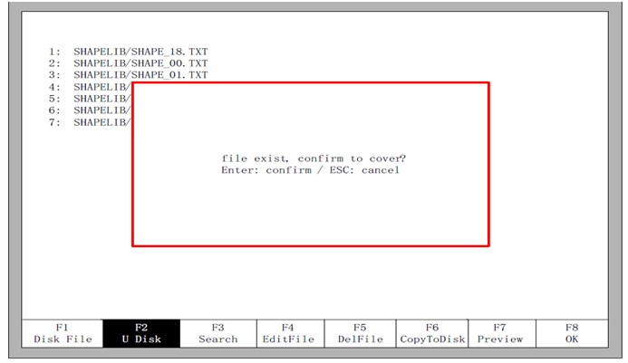
U disk operating procedures
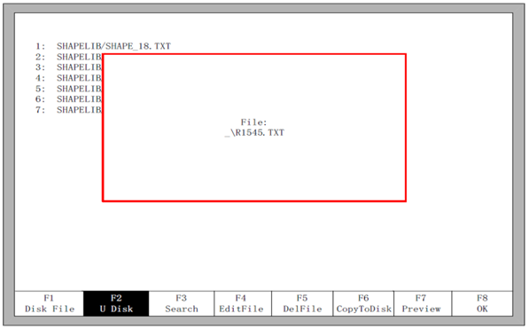
①Enter the main interface,press F2 to folder
②press F2 to U disk file
③press ![]() ,(F1 shape view),press F8 confirm。Press F6 copy to disk,then press F8 Confirm 。
,(F1 shape view),press F8 confirm。Press F6 copy to disk,then press F8 Confirm 。
Plasma、Flame operating procedures
Plasma cutting
1.switch mode(press ![]() )
)
2.make sure keep giving compressed air (0.4Mpa-0.6Mpa)
3.check Arc votlage,piercing time(refer below form)
4.setting INS height(refer below form)
5.note cutting speed and currency(refer below form)
| THICKNESS(mm) 板材厚度 |
nozzle size 喷嘴孔径 |
CURRENT(A) 电流 |
AR Number 弧压 |
CUTTING SPEED ( mm/min ) 切割速度 |
|
torch-to-work distance | |||||||||||||||||||||||||||||||
| 1-2.Smm | 1.1 | 63A | 120 | 6000-7500 | 0.1S |
3-5mm |
|||||||||||||||||||||||||||||||
| 3mm | 1.1 or 1.3 | 63A | 3200 | 0.1S | |||||||||||||||||||||||||||||||||
| 4mm | 1.3 | 63A | 2700 | 0.2S | |||||||||||||||||||||||||||||||||
| 5mm | 1.5 | 63A | 1600 | 0.2S | |||||||||||||||||||||||||||||||||
| 6mm | 1.5 | 63A | 125 | 1200 | 0.2S | ||||||||||||||||||||||||||||||||
| 7mm | 1.5 | 100A | 135 | 2500 | 0.2S | ||||||||||||||||||||||||||||||||
| 8mm | 1.7 | 100A | 140 | 1800 | 0.2S | ||||||||||||||||||||||||||||||||
| 10mm | 1.7 | 120A | 150 | 1000 | 0.2S | ||||||||||||||||||||||||||||||||
| 12mm | 1.7 | 120A | 800 | 0.3S | |||||||||||||||||||||||||||||||||
| 16mm | 1.9 | 120A | 155 | 600 | 0.3S |
3-5MM |
|||||||||||||||||||||||||||||||
| 18mm | 1.9 | 160A | 1200 | 0.3S | |||||||||||||||||||||||||||||||||
| 20mm | 2.1 | 160A | 700 | 0.3S | |||||||||||||||||||||||||||||||||
| 25mm | 2.1 | 200A | 160 | 800 | 0.3S | ||||||||||||||||||||||||||||||||
| 30mm | 2.1 | 200A | 600 | 0.3S | |||||||||||||||||||||||||||||||||
| 35mm | 2.1 | 200A | 300 | 0.3S | |||||||||||||||||||||||||||||||||
How To Maintain Portable Plasma cutting machine?
Plasma Common Faults And Solutions
Its very normal condition it has faults alarm during the use. following solution could help you some
In the process of use, the possible failure phenomena and solutions are as follows:
| No. | Fault phenomena | Reason | Solution | |||||||||||||||||||||||||||||||||||||||||||||||
| 1 | Display is not working | Power supply is down | 1. Check the connection of Power supply | |||||||||||||||||||||||||||||||||||||||||||||||
| 2 | Motor is not working | Limit signal may lock it down | 1. Check the up/down limit signal 2. Over-current protection may Lock the motor chips down. |
|||||||||||||||||||||||||||||||||||||||||||||||
| 3 | Motor is working but get blocked again |
Motor chips have over- Current protection | 1. Check the mechanical structure Is locked down or not. | |||||||||||||||||||||||||||||||||||||||||||||||
| 4 | After THC is on, the motor keep rising | The collision signal cause that | 1. Check the connection of proximity switch, check the parameter P13, L08 or L09 is set correctly or not. If the setting all correct, please make sure the red light on the proximity switch is on before it goes off. 2. Check the condition of proximity switch. 3. Check the connection between retaining cap. When the torch is not touching plate, the collision signal should not be there. |
|||||||||||||||||||||||||||||||||||||||||||||||
| 5 | Arc-Voltage Control is not stable | 1. Check the grounding. 2. Check the plasma power, the cooling liquid is leaking or not. |
||||||||||||||||||||||||||||||||||||||||||||||||
| 6 | The arcing activate before the IHS is done | It usually happened when under the control of the direct arcing signal |
1. Extend the IHS time of CNC | |||||||||||||||||||||||||||||||||||||||||||||||
| 7 | The arcing cannot start after its IHS | The plasma power ssource doesn’t work, or the arcing relay doesn’t close. | 1. Disconnect the wiring between THC and arcing relay, then short-circuit the arcing wiring on the a pow See your power source can arcing normal or not. 2. If your plasma power source is in good condition, check the arcing relay on your THC. |
|||||||||||||||||||||||||||||||||||||||||||||||
| 8 | The torch can’t light up | 1. Check the plasma power source working condition 2. Check the IHS Height is too high or too low. 3. Check the cutting consumable. 4. When using the retaining cap, the slug may spurt to the torch cause the short circuit. |
||||||||||||||||||||||||||||||||||||||||||||||||
| 9 | When the CNC start cutting, the torch falls to the plate | The arc voltage is too high | 1. Increase the setting arc voltage. 2. Increase the auto THC time on CNC. 3. Check the corner signal on CNC or auto signal. The auto THC signal should not be sent on the beginning of the cutting |
|||||||||||||||||||||||||||||||||||||||||||||||
| 10 | The arcing is off as soon as the piercing moves to the next hole |
1. The delay time is too long. (Before the CNC moves, the arc will be off easily if your torch stay at the position of pierce too long). | ||||||||||||||||||||||||||||||||||||||||||||||||
| 11 | Auto IHS, the torch won’t lift up after it hit the plate | The collision signal wasn’t sent or IHS height | 1. Check the collision signal works normally or not (Check the working status of proximity switch or retaining cap). 2. Check the IHS height time setting is too small. |
|||||||||||||||||||||||||||||||||||||||||||||||
| 12 | The torch easily hit the plate during the cutting. |
The setting voltage is too small. | 1. Increase the setting arc voltage. | |||||||||||||||||||||||||||||||||||||||||||||||
| 13 | The torch shaking during the height control. |
Sensitivity is too high | 1. Lower the parameter P07 Sensitivity. | |||||||||||||||||||||||||||||||||||||||||||||||
| 14 | On the steep bevel, the cutting voltage is hard to be track. |
Sensitivity is too low. The speed of lifting motor is too slow |
1. Increase the parameter P07 Sensitivity. 2. Switch to a faster speed lifting motor. |
|||||||||||||||||||||||||||||||||||||||||||||||
| 15 | The CNC doesn’t pause when the arc | After arc break alarm, the voltage did not | 1.The CNC could get the arcing signal feedback from the plasma itself. | |||||||||||||||||||||||||||||||||||||||||||||||
| break during the cutting process. | go down cause the THC still getting the voltage. |
|||||||||||||||||||||||||||||||||||||||||||||||||
| 16 | The screens shows “LIC” after power up | The data storage has an error | 1. Please return to supplier for repair. | |||||||||||||||||||||||||||||||||||||||||||||||
| 17 | During the upgrade, The device no respond after press Enter |
The reading speed of the USB doesn’t match | 1. Restart your device and re-upgrade. 2. Change to the another USB drive. |
|||||||||||||||||||||||||||||||||||||||||||||||
Conclude:
Don’t modify set parameter by yourself espcially to THC.
if you have any question you can contact with us.Hopefully manual book could help you a lot
if you want vidoes for faimilar machine contact with us.